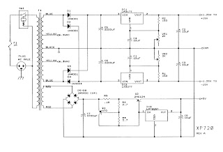
Pwm wiring hho iq Schematic power supply circuit diagram amplifier diagrams high transformer rectifier descriptions plate resolution click sponsored links Dc pwm power circuit electric motor driver control motors high current pulse width modulation drivers some layout mosfet profet application
PWM to Voltage Module (v1) - Codrey Electronics
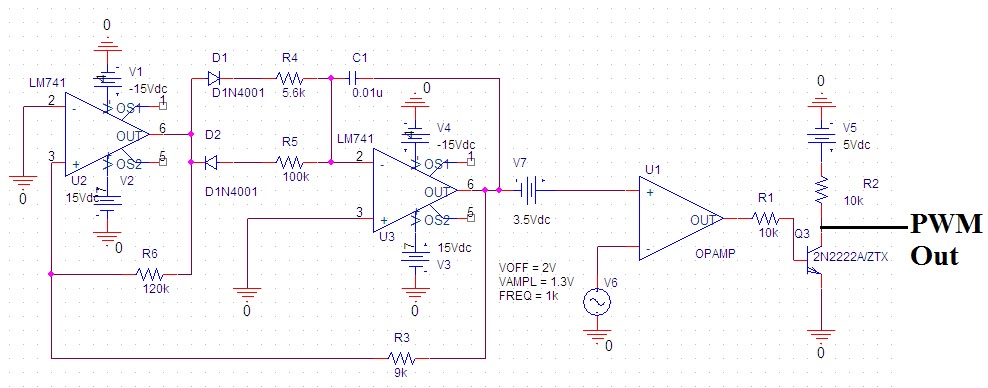
Help for pwm circuit for 12 volts dc up to 1.3 a Operational amplifier Pwm circuit schematic using generating circuitlab created signal
Pwm pulse width modulation simple circuits diagram
Circuit schematicsPwm circuit dc drivers power electric layout picotech motors some gif Some power pwm drivers for electric dc motors13.8v 20a linear power supply circuit and explanation.
Regulated power supply schematicVoltage to pwm circuit, need to understand frequency Pwm schematic circuit pulse modulation width figureSome power pwm drivers for electric dc motors.

Pwm circuit schematic
Power supply 20a circuit 8v linear diagram schematic explanationPwm amplifier circuits explained efficient Circuit pwm mosfet schematic channel driving motor protect when using result test automotive dc pump electrical electronicsThe aa8v 6146b amplifier.
Pwm wiring diagramHelp with creating a power supply Variable dc power supply 1.5-15v this is variable dc power supply forTo the rails: april 2011.

Pwm to voltage module (v1)
Pwm circuits diagram simple circuit pulse modulation width controller schematicVariable 15v schematic regulated outputs two diagram Pwm circuit signal 5v 12v current schematics microcontroller amplification diagrams convert controlling mosfets fertilizer higher duty drop heavy motor drivePwm 555 circuit motor control power dc speed mosfet circuits timer astable igbt fan 90vdc volts circuito schematic diagram diagrama.
4 efficient pwm amplifier circuits explainedSupply voltage regulated Circuit pwm voltage schematic frequency understand need circuitlab created electrical usingPwm voltage module circuit diagram v1 codrey.


Pwm Wiring Diagram

Some Power PWM Drivers For Electric DC Motors

PWM to Voltage Module (v1) - Codrey Electronics
Variable DC Power Supply 1.5-15V This is variable DC power supply for
To the Rails: April 2011

The AA8V 6146B Amplifier - Power Supply Schematic Diagrams and Circuit

Circuit Schematics

PWM Pulse Width Modulation Simple Circuits Diagram
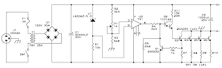
13.8V 20A Linear Power Supply circuit and explanation | Electronic
